Swerve Drive train
Overview
This was my Highschool capstone project.
The intention of the project was to redesign our High school robotics team drive train. We wanted to make the drive train more serviceable, reduce the weight per module, and reduce the cost per module. In the process Rose McNamee, Dustin Steedsman, and Myself with the guidance from some mentors form John Deere Electronic Solutions Learned how to model in Creo 3.
Research
We started with collecting images and ideas from the FRC world championships. We talked to the best FRC teams with swerve drive.
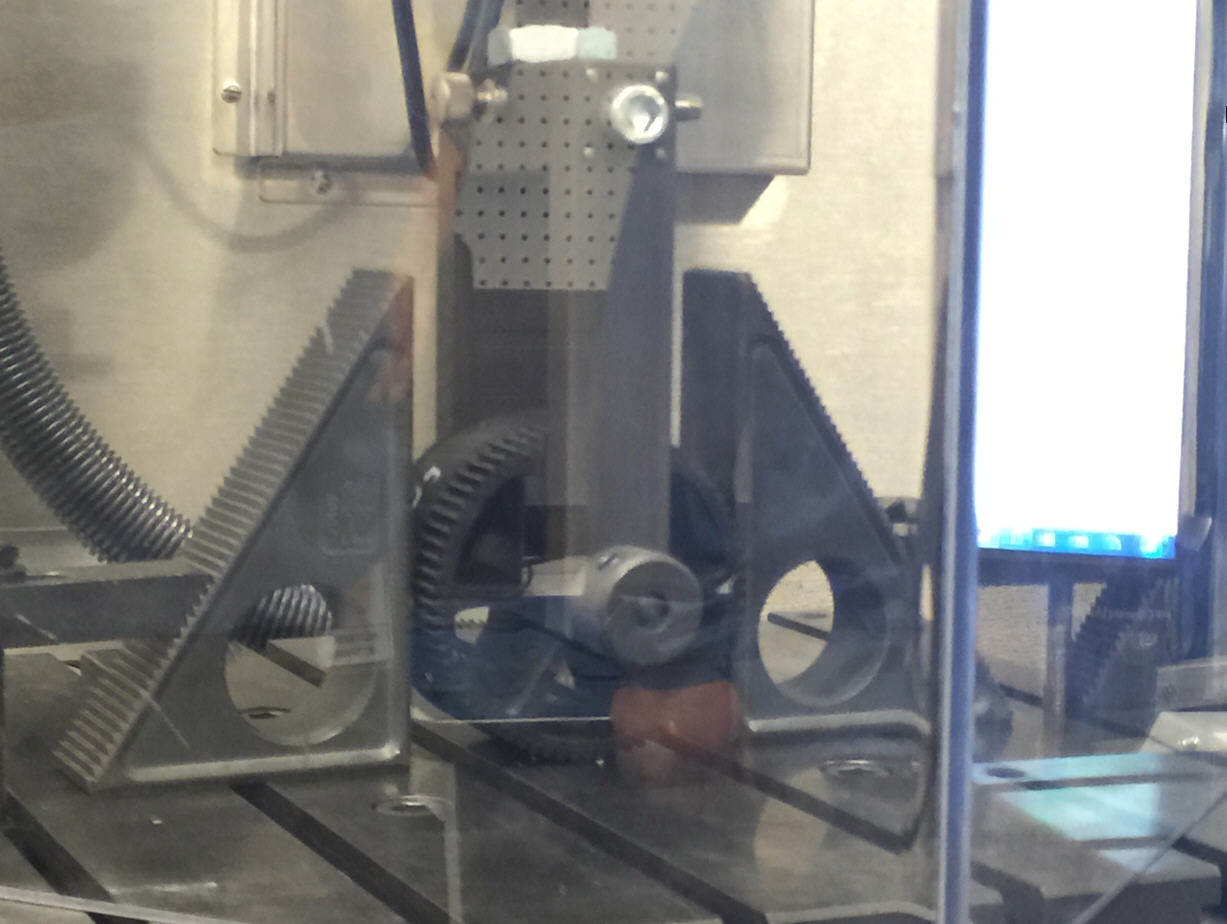
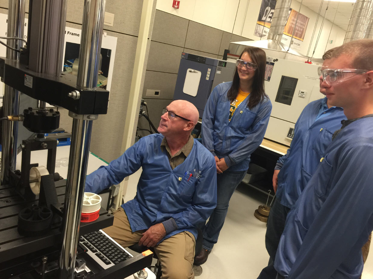
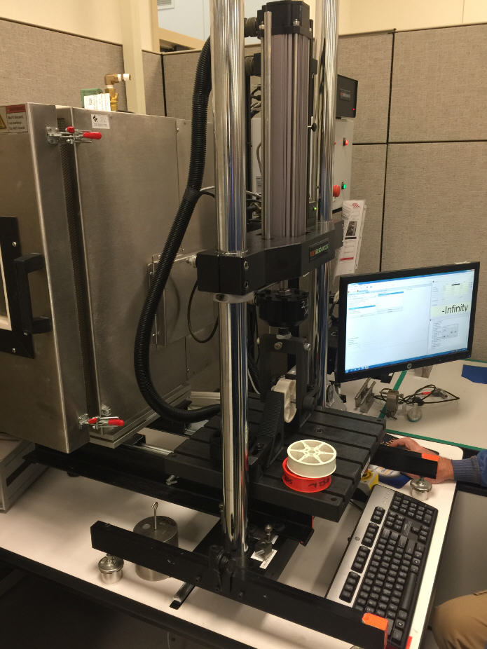
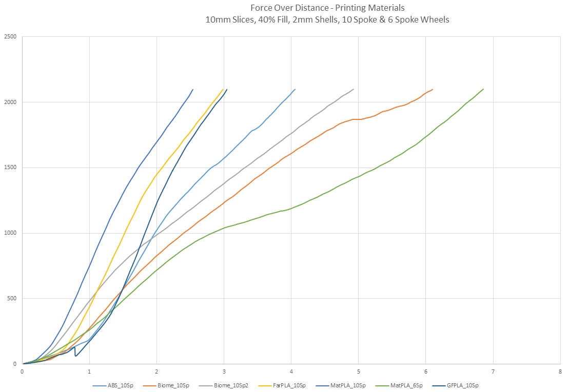
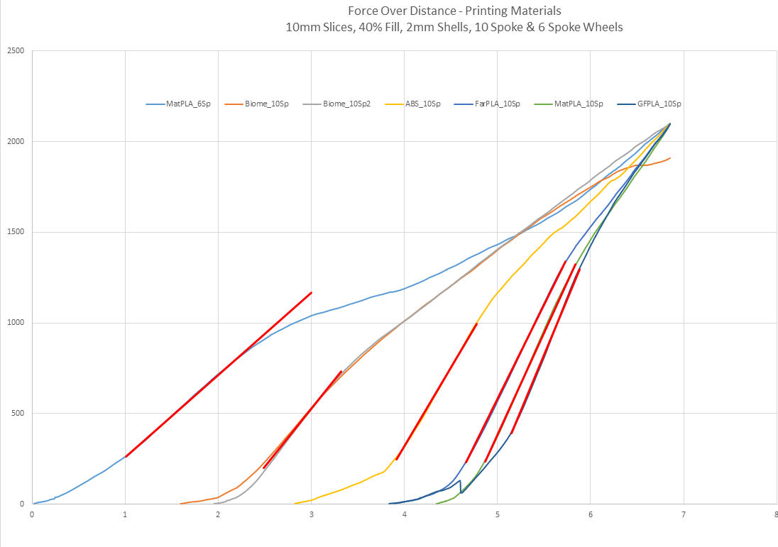
We knew we wanted to use 3D printed materials to help reduce the weight of each module which would enable the robot more weight for other mechanisms. So We went to John Deere Electronic Solutions and researched the strength of various 3D printer filaments.
The data we collected:
Designing
After collecting some data on which filament to use we started designing our swerve drive.
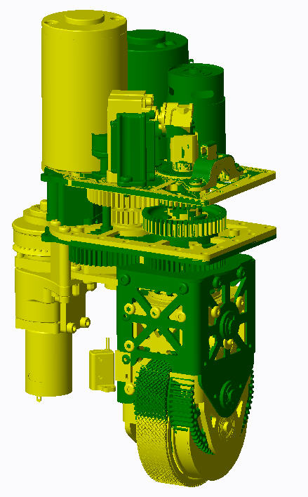
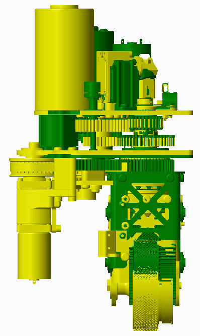
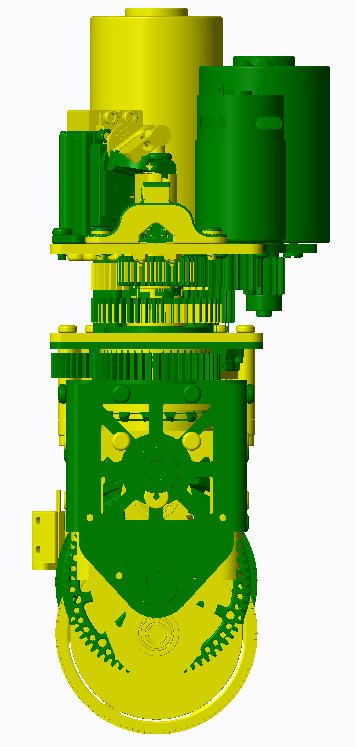
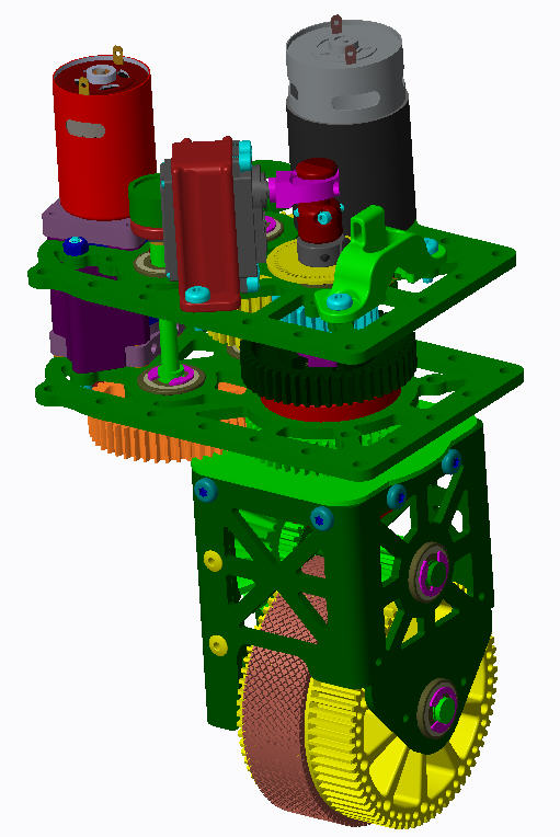
Here you can see the comparison of the our swerve module in Green and the teams old module in yellow:
We made the following improvements:
- Reduced the height of the module.
- Reduced the chance of damage to the steering motor by placing away from the floor.
- Created mount points for a couple different drive motor configurations including a Cim, MiniCIM, and 775 motor.
- Place steering Potentiometer on top of the module to reduce damage to the unit.
- Strengthened the mounting of the steering motor.
- Cut the weight by 40% by using 3D printed parts.
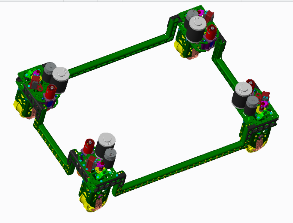
CAD Model:
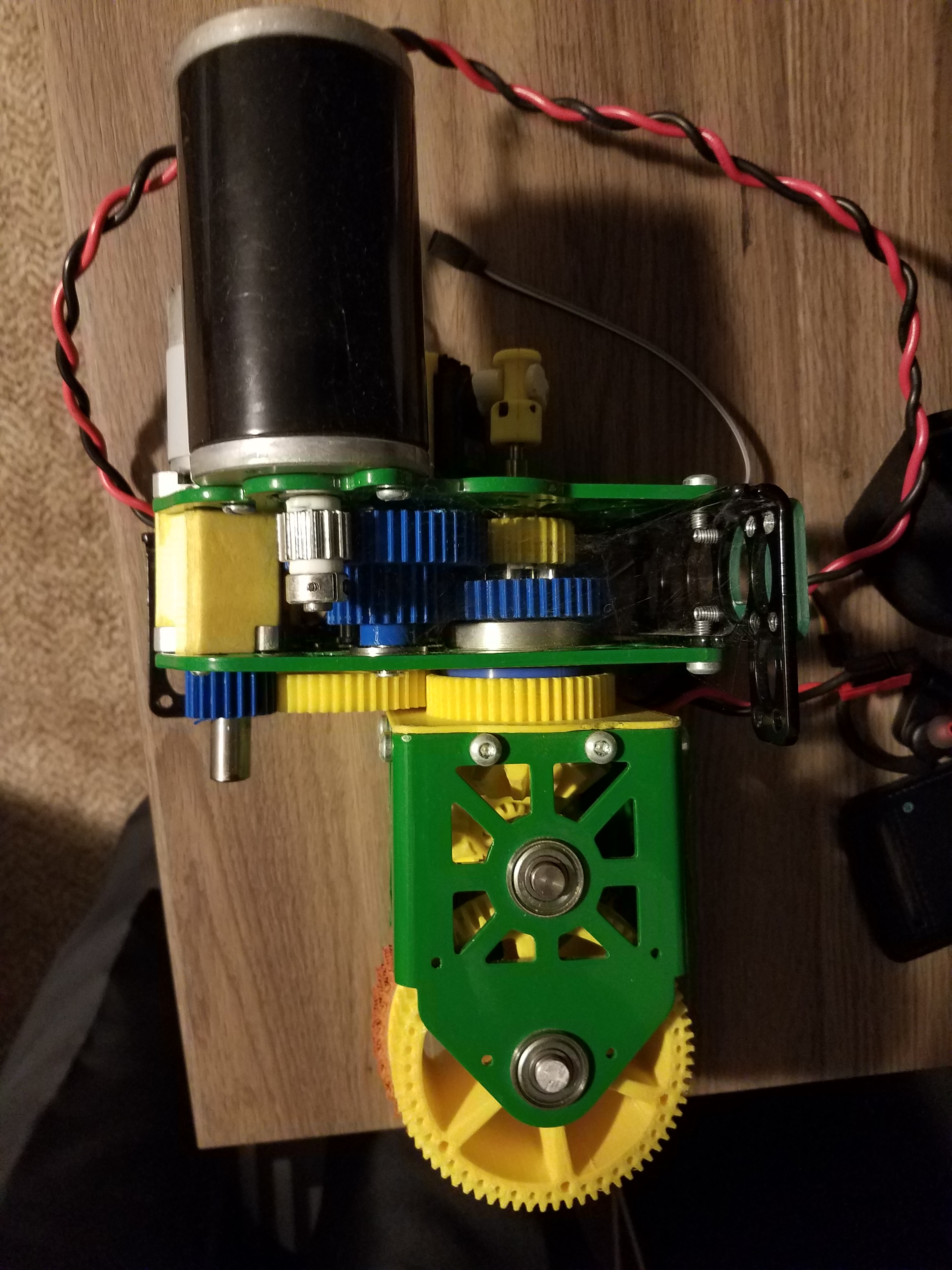
Completed Module
Items I learned
- Java
- Source Control
- CAD modeling in Creo
- 3D Printing
Timeline: May 2015 to December 2015
Partners/contributors: Rose McNamee, Dustin Steedsman
Teachers/mentors: Brad Poppe, Lee Johnson, Brad Mackowick, David Lindner
